Enhanced oil recovery (EOR) setup - high pressure (no pumps included)

From €2,025.00

To €10,593.00

In stock

€2,025.00

per Bundle

1 x Fluidic Connect 4515 chip holder - topconnect   + €1,590.00
+ 0
More information
1 x Fluidic Connect 4515 stainless steel connection kit   + €435.00
+ 0
More information

* Required Fields

This setup is an easy way to start your research. We already assembled all the right components you need for enhanced oil recovery research using pressures between 5 and ~80 bar.

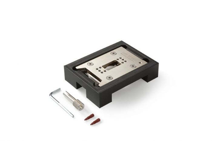
This setup contains a chip holder, chips for enhanced oil recovery (EOR) and tubing. The only thing left for you to do is to select the EOR-chip of your choice: with a uniform, random or physical rock structure. These microfluidic chips can be used in enhanced oil recovery research, reservoir engineering or environmental research. They are used to verify simulation models of rock-pore structures in the EOR field.

More Information
Unit of measurementBundle
ApplicationEnhanced Oil Recovery
Icon Label Description Type Size Download
pdf EOR information Additional information on the Uniform, Random and Physical rock network structures. pdf 257.8 KB Download
PDF 11002978 / 11002198 / EOR.UN.20.2 - Drawing Drawing for the EOR porous medium chip with Uniform Pore Network. Items 11002978 and 11002198 PDF 378.2 KB Download
PDF 11002977 / 11002199 / EOR.RN.20.2 - Drawing Drawing for the EOR porous medium chip with Random Pore Network. Items 11002977 and 11002199 PDF 123.7 KB Download
Customer Questions
Which pressure and temperature can the EOR chip hold?
The EOR chip itself is manufactured from glass an can easily withstand up to 300⁰C. The chips are supplied in a black fluidic cartridge however. This cartridge can widthstand up to 80⁰C. No sealant is used, the two layers of glass are fusion bonded together. The chip can withstand easily up to 100 bar. The external interfacing is more critical however. Our Fluidic Connect holder offers the largest pressure, up to 80 bars (maybe less at elevated temperatures). Please note that it might be helpful to practice a little with the Fluidic Connect holder first. You need to get the feeling to apply not too much force, which might break the chip, but enough to obtain sufficient sealing. It might be necessary to tighten a bit more when pressure and temperature are increased. Please remove the pressure before additional tightening.
I'm using the Fluidic Connect 4515 holder (part of high pressure bundle), what alignment and fluidic port should I use?
The fluidic ports are on positions 3,8
Alignment can be done on positions 2,7 (or 4,9).
I have some leakage using the Fluidic Connect 4515, what can I do?
Leak free connections with the Fluidic Connect 4515 can be a bit challenging.

There are some things to consider: The PEEK connectors are modified versions of a standard connector. We add some additional thread to the connectors.

The thread length should be ~6-7mm. Please check if the thread link is correct as first. Please assemble according to this manual: https://store.micronit.com/mpattachment/file/download/id/15/ (page 10) The fitting should be tightened on a special hole position at first assembly. This is in the top left corner of the holder. This will assure sufficient force can be applied to compress the fitting without damaging a real chip. Fittings are limited in amount of use. Key importance is that they are clean and free of particle. Salt residues will cause leakage. If issues occur it’s important to use clean fittings. It might be possible that some small re-tightening is required during slow buildup of pressure. Especially at elevated temperatures some relaxation might occur. Please always remove pressure before additional tightening.  
What's important in selection of a suitable microscope objective (regular bottom thickness chips)?
A inverted miscope is recommend, as most surface for observation is on the bottom (non-inlet side).
The objective working distance is a critical parameter for selection of an objective.  Most default objectives are indented for a #1.5 cover slip which is only 170µm thick, where the thickness below channel is mostly in the range of 400-900µm.   
Those objectives with longer working distance are often called non-coverglass objectives.
Where possible we would recommend to work dry. In most cases it should be possible to use the channel edge or other well defined point  as reference for manual size corrections, this would reduce the need for corrections by the objective.
What is the roughness of the etched structures?
Wet etched structures are extremely smooth and have a roughness in Angstrom range. The structures are fully optical transparent. 
Large roughness for structures in glass chips is typical observed for structures manufactured by use of laser assisted manufacturing techniques or abrasion-based techniques like powder blasting. Almost all catalogue products from Micronit are manufactured using wet etching to create full transparent channels without substantial roughness. 
Would you like to submit a question? Please login first.
Copyright © 2020-present Micronit B.V. All rights reserved.