Chips for Electrical Impedance Spectroscopy - Top connect
SKU
11001552
Availability:
In stock
€1,095.00
per pack of 2
Pack of two Chips for Electrical Impedance Spectroscopy (EIS) measurements.

Introduction to EIS Combined with Microfluidics
In the Electrical Impedance Spectroscopy (EIS) chip, microfluidics transport a medium that can contain cells or particles over a collection of electrodes. One set of electrodes contains an excitation signal (typically an accumulating current), while the second set of electrodes registers the effect of the cells or particles passing by on the signal. Impedance is the opposition to alternating current presented by the combined effect of resistance and reactance in a circuit. In general, it depends on the frequency of the sinusoidal voltage. A passing cell or particle causes a difference in impedance, allowing for counting. However, the impedance difference also provides information about the cell or particle itself, acting as a sort of fingerprint that can be used to distinguish cells or particles with specific properties. The frequency of the excitation signal used has an influence on the ability to distinguish cells or particles.
Application Possibilities.
This chip, equipped with a flow channel and electrodes for Electrical Impedance Spectroscopy (EIS)-based measurements, aims to explore the potential of Electrical Impedance Spectroscopy for your own application. EIS is already commercially applied as a measurement technique in the following areas:
- Cell and particle counting and characterization, which is an important aspect of flow cytometry.
- Bacterial counting in (drinking) water.
- Counting of poles in air.
The Chip
The chip is a hermetically bonded triple-layer device:
- The top layer is a glass layer with a thickness of 700µm and contains, besides holes and openings, a set of Pt-electrodes.
- The middle layer consists of a 30µm dry film resist layer and contains the side walls of the channel.
- The bottom layer also contains a set of Pt-electrodes.
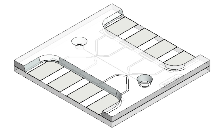
See the drawing for more details.
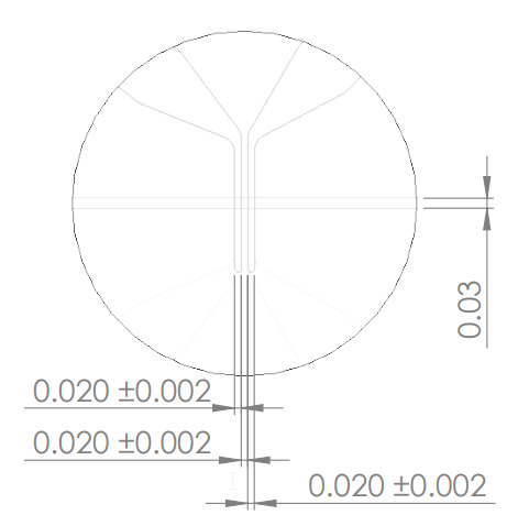
In total, the chips contain four sets of two electrodes (eight individual electrodes):
- Inlet side, top side of the channel
- Outlet side, top side of the channel
- Inlet side, bottom side of the channel
- Outlet side, bottom side of the channel
Each electrode set has the following structure:
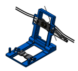
What do you need to get started?
- Pack of chips
- or a set of EIS insert when a chip holder is already available.
(8 cable assemblies are included with the holder) - Pumps—basic syringe pumps should work, but pressure-based pumps can offer more control. When both the inlet and outlet are pressurized, the flow can be stopped instantly.
- Zurich instruments HF2LI
- Zurich instruments Current Aplifier HF2TA
- (Inverted) microscope or suitable USB microscope.
- Computer with optional pump control software and LabOne (from Zurich Intruments)
Customizations
Existing commercial applications use a range of different chip designs depending on what's measured. It's likely that for the most optimal measurement result, some application-specific customization might be required. We are happy to help with further customizations as part of your product development.
| Unit of measurement | pack of 2 |
|---|---|
| Chip thickness | 1.4mm |
| Number of inlets | 1 |
| Number of outlets | 1 |
| Channel width | 30µm |
| Electrode material | Platinum |
| Icon | Label | Description | Type | Size | Download |
|---|---|---|---|---|---|
 | Drawing EIS - Top Connect Chip | 89.1 KB | Download |
Customer Questions
We found other products you might like!